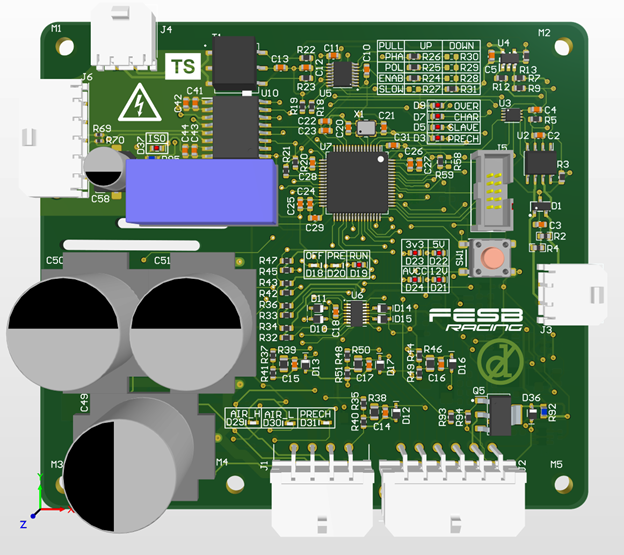
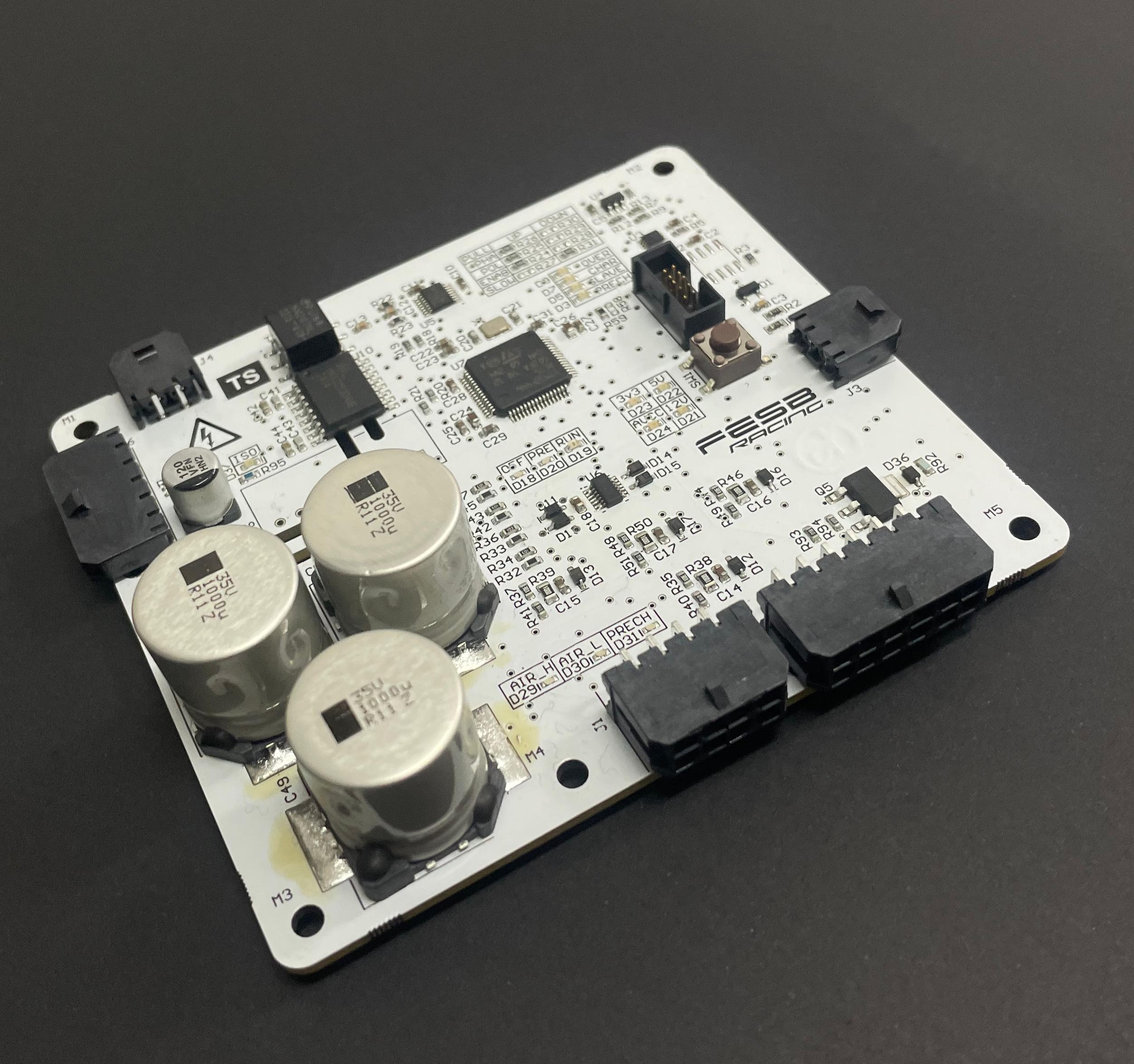
Our battery monitoring system is built around a master-slave topology, with the master PCB serving as the main control unit for the entire accumulator. At the center of the board is an STM32F446 microcontroller, which provides the processing power and communication interfaces needed to handle multiple real-time tasks. The master is in charge of collecting and processing cell voltage and temperature data, keeping track of the accumulator current, and running the control routines that ensure safe and efficient operation.
Beyond that, it also takes care of cell balancing, making sure the cells stay evenly charged to extend pack life and maintain performance. It handles communication with higher-level vehicle control units, carries out fault detection and protection functions, and coordinates the activity of the BMS slaves without relying on them for critical decisions. With all of these tasks centralized, the master becomes the core of the system, tying together data acquisition, monitoring, and control into one reliable platform.
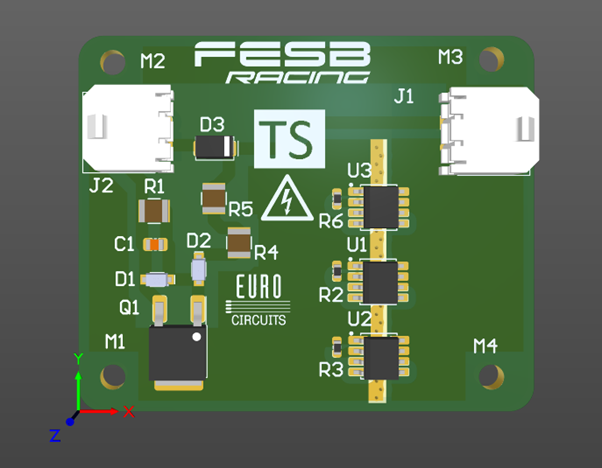
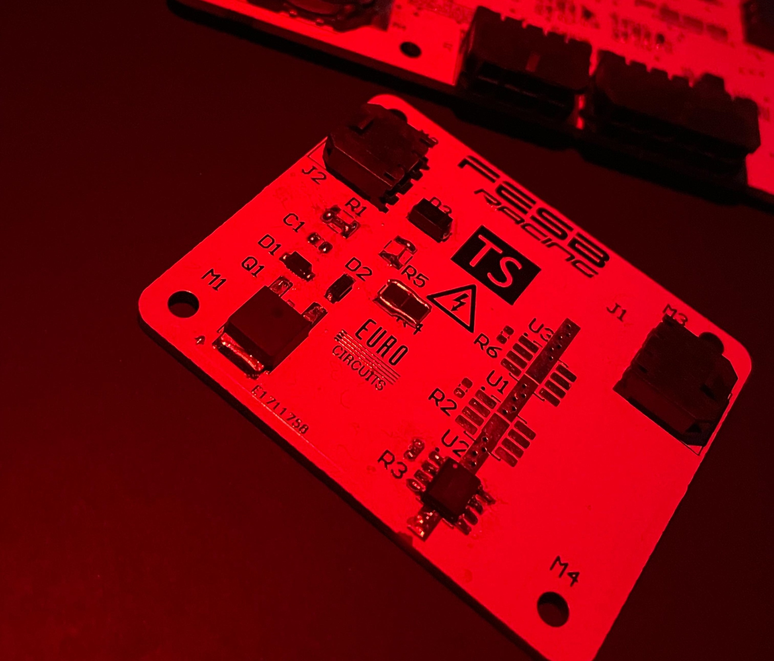
Voltage Indicator (VI) Design
Voltage Indicator (VI) is a key safety system on our electric vehicle. Its function is to activate a visual indicator on the vehicle when the voltage on the Tractive System (TS) exceeds or reaches the threshold of 50 V, signaling a potential electrical hazard.
One of the main challenges in designing this circuit was ensuring its power supply across a wide voltage range—from 5 V all the way up to 500 V. We solved this problem by using the RM9003B, which enables a constant current supply to the circuit at voltages up to 600 V. For voltage detection and indicator control, we implemented a simple circuit consisting of a voltage divider and a zener diode on the MOSFET gate, achieving reliable and efficient indicator activation.
Kolačiće koristimo kako bismo poboljšali vaše iskustvo u skladu s GDPR odredbom. Kolačići se koriste kako bi vam ponudili kvalitetu usluge i ostale potrebne funkcionalnosti. Korištenjem ove web stranice pristajete na korištenje kolačića. Accept
Privacy Overview
This website uses cookies to improve your experience while you navigate through the website. Out of these, the cookies that are categorized as necessary are stored on your browser as they are essential for the working of basic functionalities of the website. We also use third-party cookies that help us analyze and understand how you use this website. These cookies will be stored in your browser only with your consent. You also have the option to opt-out of these cookies. But opting out of some of these cookies may affect your browsing experience.
Necessary cookies are absolutely essential for the website to function properly. This category only includes cookies that ensures basic functionalities and security features of the website. These cookies do not store any personal information.
Any cookies that may not be particularly necessary for the website to function and is used specifically to collect user personal data via analytics, ads, other embedded contents are termed as non-necessary cookies. It is mandatory to procure user consent prior to running these cookies on your website.